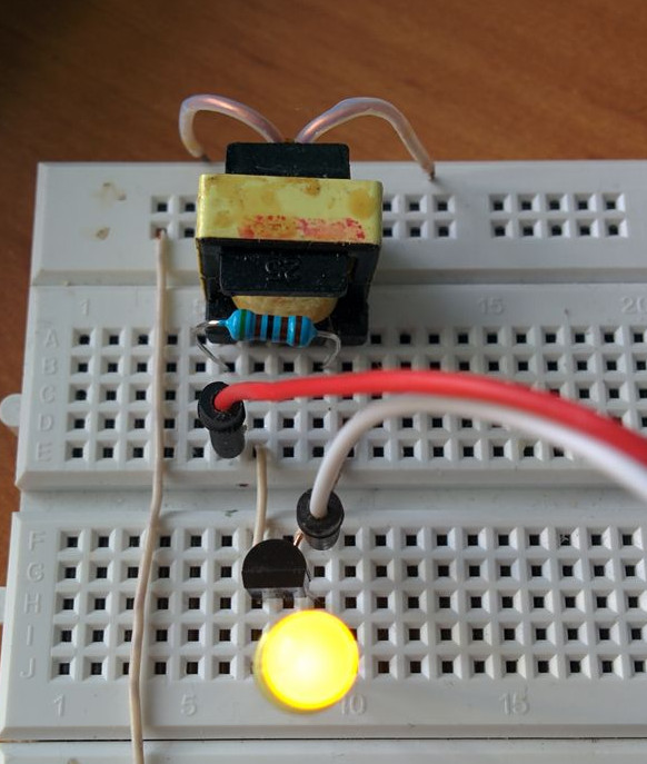
Joule thief
Citing Wikipedia:
A joule thief is a minimalist self-oscillating voltage booster that is small, low-cost, and easy to build, typically used for driving small loads. This circuit is also known by other names such as blocking oscillator, joule ringer, vampire torch.
The name comes from the fact that the circuit can work even on a battery that is almost totally depleted (0.7 V is enough). The best description of the working principle that I found is here.
It's so easy to build it that I did it just to see it live. Instead of typical toroid 1:1 transformer I used a transformer unsoldered from a broken phone charger.

Although I used a transformer that is not typical for this circuit and has unknown parameters it worked correctly. I was curious about the frequency it generates (Wikipedia states that usually it's around 50 kHz), so I tried connecting a piezoelectric membrane to it. I couldn't hear anything, so I concluded that the frequency is greater than 20 kHz or my hearing is bad.
A LED limits voltage generated by this ciruit, so it should be safe to connect it as an input of a microcontroller...
I wrote a simple program that uses external interrupt to count impulses. It turned out that the frequency is around 210 kHz, but when I switch transformer windings it goes down to 27.9 kHz. I guess that's expected for not a 1:1 transformer.
On the next day I enhanced the program to record and print input high/low timings. Here are measured times (in µs):
1 1,75
0 2,98
1 1,72
0 3,00
...
1 1,73
0 3,00
And here are measured times for switched windings:
1 9,68
0 26,19
1 9,69
0 26,19
...
1 9,68
0 26,19
The source code is as usually on Github.
Question 1.
How to use input capture on STM32? Any piece of advice?