LCD Screens
Nothing really interesting here. I just want to document how to connect two
LCD screens to a blue pill.
Actually it's not a blue pill.
It's black.
Some pins are connected differently. E.g. onboard LED is not on PC13,
but on PB12.
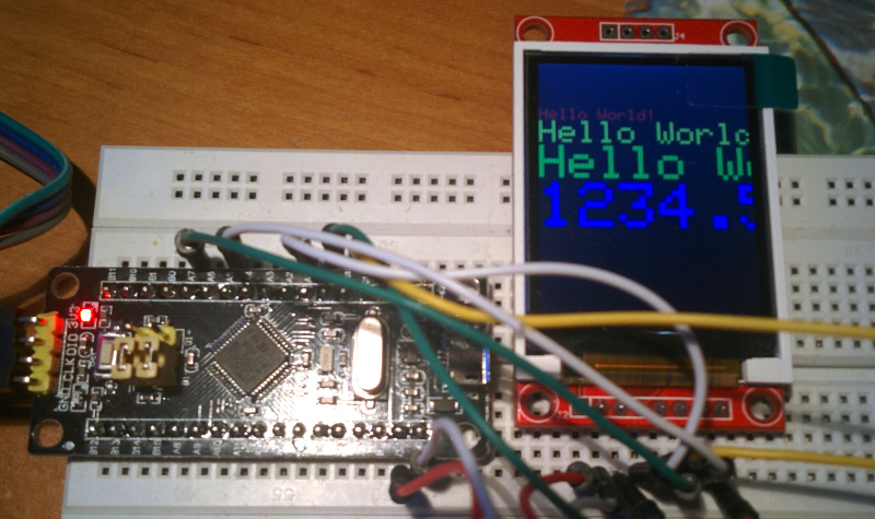
ST7735 1.8'' TFT LCD
This one has 128x160 resolution.

Connect as follows.
STM32  3.3 --- VCC  LCD
       GND --- GND
       AO  --- CS
       A1  --- RESET
       C13 --- AO
       A7  --- SDA
       A5  --- SCK
       3.3 --- LED
I used Adafruit_GFX library version ported to STM32. To test it I took example from original Adafruit library and changed pin numbers.
--- libraries/Adafruit_ST7735/examples/graphicstest/graphicstest.ino    2018-03-30 22:13:14.870036019 +0200
+++ st7735-test/st7735-test.ino 2018-03-31 22:51:22.025625036 +0200
@@ -21,17 +21,17 @@
   MIT license, all text above must be included in any redistribution
  ****************************************************/

-#include <Adafruit_GFX.h>    // Core graphics library
+#include <Adafruit_GFX_AS.h>    // Core graphics library
 #include <Adafruit_ST7735.h> // Hardware-specific library
 #include <SPI.h>


 // For the breakout, you can use any 2 or 3 pins
 // These pins will also work for the 1.8" TFT shield
-#define TFT_CS     10
-#define TFT_RST    9  // you can also connect this to the Arduino reset
+#define TFT_CS     PA0
+#define TFT_RST    PA1  // you can also connect this to the Arduino reset
                       // in which case, set this #define pin to 0!
-#define TFT_DC     8
+#define TFT_DC     PC13 // A0

 // Option 1 (recommended): must use the hardware SPI pins
 // (for UNO thats sclk = 13 and sid = 11) and pin 10 must be
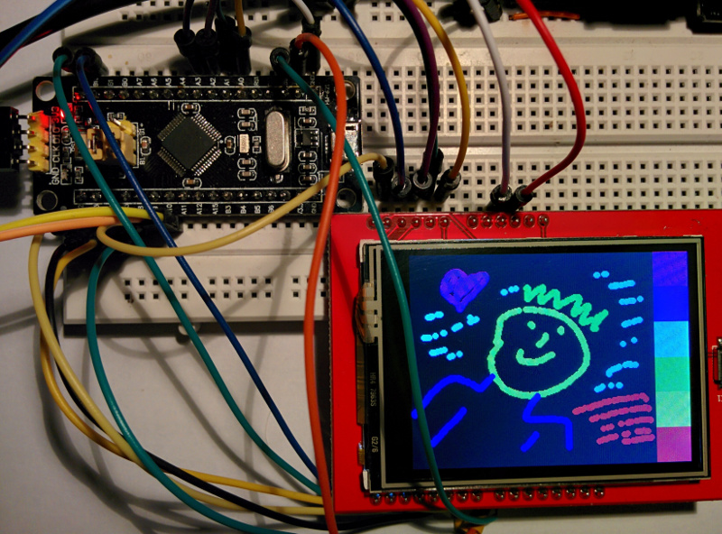
ILI93.. 2.4'' TFT LCD
This one has 320x240 resolution and is touch sensitive. Image can be sent
serially or by 8-bit data bus. I used data bus for the speed sake.

Adafruit library port can be found here. It was modified by an author of this instructable to use different pins. Unfortunately I couldn't find it on Github. There is a zip file to download.
An author of the first library admits that this one is better. I'm thinking about porting oscilloscope code to it.
Some documentation about display and drivers can be found here.