- 018 How to stack
- 017 Brainf___ machine
- 016 Formal verification
- 015 How to count
- 014 Connecting FPGA to a computer
- 013 Binary numeric screen mode
- 012 VESA output by FPGA
- 011 Programming Xilinx Spartan 6
- 010 Learning basics of Verilog
- 009 Improvements in the blog engine
- 008 Migrating to AWS
- 007 LCD screens
- 006 Joule thief
- 005 Hall effect sensors
- 004 Constant acceleration revisited
- 003 Digital pendulum
- 002 Driving stepper motor
- 001 Play with forth and STM32
- 000 Hello world
Learning basics of Verilog with Verilator and DigitalJS
What is Verilog?
To cite Wikipedia:
Verilog, standardized as IEEE 1364, is a hardware description language (HDL) used to model electronic systems. It is most commonly used in the design and verification of digital circuits at the register-transfer level of abstraction.
What is Verilator?
To cite authors of Verilator:
Verilator is the fastest free Verilog HDL simulator, and outperforms most commercial simulators. Verilator compiles synthesizable SystemVerilog (generally not test-bench code), plus some SystemVerilog and Synthesis assertions into single- or multithreaded C++ or SystemC code.
What is DigitalJS?
To cite Tilk who is an author of DigitalJS:
DigitalJS is a digital circuit simulator implemented in Javascript. It is designed to simulate circuits synthesized by hardware design tools like Yosys, and it has a companion project yosys2digitaljs, which converts Yosys output files to DigitalJS. It is also intended to be a teaching tool, therefore readability and ease of inspection is one of top concerns for the project.
Modules
Verilog module is a reusable black box with inputs and outputs. Module has name, and generally it should have both inputs and outputs:
module our;
  input  A;
  output X;

  ...
endmodule
Modules can be
- stateless – in that case output depends only on inputs;
- stateful – when module has internal state that can change.
We will start our Verilog exploration by looking at stateless modules.
Combinatorial logic
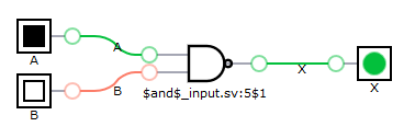
Stateless modules are used to compute combinatorial logic. Let's define module that calculates NAND logic function.
First, let's look at Verilog code:
module top(X, A, B);
  input   A, B;
  output  X;

  assign  X = ~(A & B);
endmodule
To check our first module, we can go to Yosys2digitaljs web application, paste Verilog code, and we get synthesized circuit visualization. Just a NAND gate.
To test it with Verilator, we need C++ (or SystemC, but I'll stick with C++) code to run simulation:
#include <iostream>

#include "Vtop.h"

int main(int argc, char **argv, char **env) {
  Verilated::commandArgs(argc, argv);

  // init top verilog instance
  Vtop top;

  for (int a = 0; a < 2; ++a) {
    for (int b = 0; b < 2; ++b) {
      top.A = a;
      top.B = b;
      top.eval();

      std::cout << "a=" << a
        << " b=" << b
        << " x=" << (int)top.X
        << std::endl;

      if (Verilated::gotFinish()) exit(0);
    }
  }

  exit(0);
}
To run it we need to execute 3 steps:
verilator -Wall --trace --cc top.v --exe top.cpp # generate c++ code from verilog
make -C obj_dir -j -f Vtop.mk Vtop # compile c++ code
obj_dir/Vtop # run it
The outcome is correct:
a=0 b=0 x=1
a=0 b=1 x=1
a=1 b=0 x=1
a=1 b=1 x=0
Something to remember, but I don't want to elaborate on that:
assignstatements are not sequential. It makes no sense to overwrite previously defined value. All assigns should create directed graph from inputs to outputs with no cycles.- There are tasks and functions in Verilog (useful to include).
- There are
inoutmodule ports.
Types and Expressions
Verilog defines a single base data type which has the following four values:
- 0 - represents a logic zero or false condition
- 1 - represents a logic one or true condition
- X - represents an unknown logic value
- Z - represents high-impedance state
Basic operators are similar to C operators, but there are more.
Variables can be vectors consisting of many base data type values. By using vectors of 4 bits we can transform previous example to parallel computation:
module top(X, A, B);
  input [3:0] A;
  input [3:0] B;
  output [3:0] X;

  assign  X[3:0] = ~(A[3:0] & B[3:0]);
endmodule
And test it with C++ code:
#include <iostream>
#include <bitset>

#include "Vtop.h"

int main(int argc, char **argv, char **env) {
  Verilated::commandArgs(argc, argv);

  // init top verilog instance
  Vtop top;

  top.A = 0b0011;
  top.B = 0b0101;
  top.eval();
  std::cout << "a=" << std::bitset<4>(top.A) << std::endl
    << "b=" << std::bitset<4>(top.B) << std::endl
    << "x=" << std::bitset<4>(top.X) << std::endl;

  exit(0);
}
Getting resut:
a=0011
b=0101
x=1110
Logic gates
Alternatively, we can define our NAND module by combining logic gates.
There are built it modules for basic logic gates (and, or, not, ...) that
can be combined this way. There is nand gate too, but we won't use it.
module top(X, A, B);
  input   A, B;
  wire W;
  output  X;

  and and1 (W, A, B);
  not not1 (X, W);
endmodule
Worth noting:
wire Wabove it something new. This defines internal connection point that it neither input nor output.and and1 (W, A, B)instantiates gateandand gives its instance nameand1. It hasAandBas inputs andWas output.not not1 (X, W)instantiates gatenot...
Logic gates work on vectors too. I guess gates are generic modules that work for any vector length:
module top(X, A, B);
  input [3:0] A;
  input [3:0] B;
  wire  [3:0] W;
  output [3:0] X;

  and and1 (W, A, B);
  not not1 (X, W);
endmodule
By the way, this technique can be used to combine any modules, not just logic gates.
Sequential logic
To create so called sequential logic we need state in our module.
We already know input, output and wire module declarations.
One more that we will need is reg, as in register. And indeed, reg
declarations can be used to create registers that store value.
Once we have reg declaration, we need to tell when it will change value.
To do this, we can use always @(conditions) block. Usually we want
value to change on edge of a clock cycle. E.g. we can use
always @(posedge clk) to change state of some registers at positive edge
(change from 0 to 1) of clk signal. Similarly, we can use always @(negedge clk) to change
value at negative edge of clk signal. always block will be evaluated
at any change of signal if we skip posedge and negedge keyword.
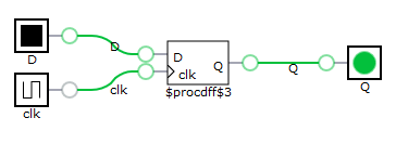
Let's consider simplest possible example:
module register(Q, D, clk);
  input   D, clk;
  output  Q;
  reg     Q;

  initial
  begin
    Q = 0;
  end

  always @(posedge clk)
  begin
    Q <= D;
  end
endmodule
Synthesis gives a single D-type filp-flop.
To see how it works, let's write simple test code:
void print(Vregister& top, int i) {
  std::cout << "i=" << i
    << " clk=" << (int)top.clk
    << " D=" << (int)top.D
    << " Q=" << (int)top.Q
    << std::endl;
}

int main(int argc, char **argv, char **env) {
  ...

  top.clk = 1;
  top.D = 0;
  top.eval();
  print(top, 0);

  top.D = 1;
  top.eval();
  print(top, 1);

  top.clk = 0;
  top.eval();
  print(top, 2);

  top.D = 0;
  top.eval();
  print(top, 3);

  top.D = 1;
  top.eval();
  print(top, 4);

  top.clk = 1;
  top.eval();
  print(top, 5);

  ...
}
An outcome is:
i=0 clk=1 D=0 Q=0
i=1 clk=1 D=1 Q=0
i=2 clk=0 D=1 Q=0
i=3 clk=0 D=0 Q=0
i=4 clk=0 D=1 Q=0
i=5 clk=1 D=1 Q=1
As we can see, state of Q has not changed until i=5, despite D has changed
several times and clk has changed once (but from positive value to negative).
You may have noticed <= in always block. It is the same as less or equal operator,
but in this contexts it is nonblocking assignment. It can be used only in always blocks.
Normal assignment (so called blocking assignment) can be used in always
blocks too, but nonblocking assignment should be used for assigning computed value to port
or register. For details, see this article.
An example: cellular automata
In this example we will write Verilog code that can simulate 1D cellular automata. Surprisingly, even 1D automata, in which state of a cell depends only on its state and state of two neighboring cells, can generate interesting patterns. When state is binary, there are only $$2^{2^3} = 256$$ possible rules for 1D automata. The most famous is rule 30, so we will use it for testing.
Single cell
We want cells to operate in phases, so we have clk signal
that is used for synchronization.
Single cell needs only 1 bit of internal state and this state is visible
as an output. This is reg out below.
(I noticed that output x and reg x declarations
can be combined into one declaration and written as output reg x,
which is more readable.)
We give 8 bit rule on input – our cells will be universal.
We need to give state of neighboring cells (left and right inputs).
Finally, we have ability to give initial state of the cell. This can be
done by setting set_state=1 and giving state value.
Logic is very simple. Value of out register can change only on positive
edge of clk signal:
- if
set_state=1, internal state is set to givenstate; - if
set_state=0, we look at number described by concatenatedright,outandleftvalues. This number gives position inrulevector that should be used as output.
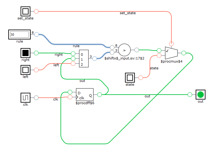
module ca_cell(clk, out, rule, left, state, set_state, right);
  input wire       clk;
  input wire [7:0] rule;

  input wire       left;
  input wire       right;

  input wire       state;
  input wire       set_state;

  output reg       out;

  always @ ( posedge clk ) begin
    if (set_state)
      out <= state;
    else
      out <= rule[{right,out,left}];
  end

endmodule
Synthesis result is pretty much what I expected. We can see
- D filp-flop to store state
- multiplexer to set given state or calculated state
- something named shiftx, what I expected also to be multiplexer, but maybe some sort of shift register can be used instead.
To test single cell, I wrote C++ test case, which is too boring to cite. Believe me, it works just fine.
Connecting cells
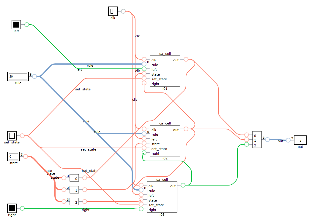
All we need to get working cellular automaton is connecting cells by wires. Connecting 8 cells is a bit lengthy, but super-simple:
module ca2(clk, out, rule, left, state, set_state, right);
  input wire       clk;
  input wire [7:0] rule;

  input wire       left;
  input wire       right;

  input wire [7:0] state;
  input wire       set_state;

  output wire [7:0] out;

  ca_cell i01(
    .clk(clk),
    .rule(rule),
    .set_state(set_state),
    .state(state[0]),
    .out(out[0]),

    .left(left),
    .right(out[1])
  );

  ca_cell i02(
    .clk(clk),
    .rule(rule),
    .set_state(set_state),
    .state(state[1]),
    .out(out[1]),

    .left(out[0]),
    .right(out[2])
  );

  ca_cell i03(
    .clk(clk),
    .rule(rule),
    .set_state(set_state),
    .state(state[2]),
    .out(out[2]),

    .left(out[1]),
    .right(out[3])
  );

  ca_cell i04(
    .clk(clk),
    .rule(rule),
    .set_state(set_state),
    .state(state[3]),
    .out(out[3]),

    .left(out[2]),
    .right(out[4])
  );

  ca_cell i05(
    .clk(clk),
    .rule(rule),
    .set_state(set_state),
    .state(state[4]),
    .out(out[4]),

    .left(out[3]),
    .right(out[5])
  );

  ca_cell i06(
    .clk(clk),
    .rule(rule),
    .set_state(set_state),
    .state(state[5]),
    .out(out[5]),

    .left(out[4]),
    .right(out[6])
  );

  ca_cell i07(
    .clk(clk),
    .rule(rule),
    .set_state(set_state),
    .state(state[6]),
    .out(out[6]),

    .left(out[5]),
    .right(out[7])
  );

  ca_cell i08(
    .clk(clk),
    .rule(rule),
    .set_state(set_state),
    .state(state[7]),
    .out(out[7]),

    .left(out[6]),
    .right(right)
  );
endmodule
For sake of readability I will visualize only three cells connected:
Now we can set it up and cycle clock in a loop to see how it evolves:
void print(Vca2& top, int i) {
    std::cout << "i=" << i
      << "\tout=" << std::bitset<8>(top.out)
      << std::endl;
}

void testCa2() {
  std::cout << "Testing ca2" << std::endl;
  int count = 0;
  Vca2 ca;

  ca.clk = 0;
  ca.rule = 30; // use rule 30
  ca.set_state = 1;
  ca.state = 16; // 00010000
  ca.eval();

  ca.clk = 1;
  ca.eval();
  print(ca, ++count);

  ca.set_state = 0;
  ca.left = 0;
  ca.right = 0;

  while (count < 10) {
    ca.clk = 0;
    ca.eval();

    ca.clk = 1;
    ca.eval();
    print(ca, ++count);
  }

}
Which gives expected outcome:
Testing ca2
i=1     out=00010000
i=2     out=00111000
i=3     out=01001100
i=4     out=11110110
i=5     out=00010011
i=6     out=00111101
i=7     out=01000101
i=8     out=11101101
i=9     out=00100101
i=10    out=01111101
More cells
It would be nice to be able to generate cells and connections by some kind of loop, wouldn't it? It is possible indeed.
module ca3(clk, out, rule, left, state, set_state, right);
  parameter WIDTH = 32; // modules can be parameterized

  input wire       clk;
  input wire [7:0] rule;

  input wire       left;
  input wire       right;

  input wire [WIDTH-1 : 0]  state;
  input wire                set_state;

  output wire [WIDTH-1 : 0] out;

  genvar i;
  generate
  for (i=0; i < WIDTH; i=i+1)
    ca_cell ith(
      .clk, // when name of port is the same as name of wire/reg, argument can be omitted
      .rule,
      .set_state,
      .state(state[i]),
      .out(out[i]),

      .left(i == 0 ? left : out[i-1]), // conditionals are allowed in generate block
      .right(i == WIDTH-1 ? right : out[i+1])
    );
  endgenerate

endmodule
Code is shorter and simulation now gives bigger, nicer result:
Testing ca3
i=1     out=00000000000000010000000000000000
i=2     out=00000000000000111000000000000000
i=3     out=00000000000001001100000000000000
i=4     out=00000000000011110110000000000000
i=5     out=00000000000100010011000000000000
i=6     out=00000000001110111101100000000000
i=7     out=00000000010010000100110000000000
i=8     out=00000000111111001111011000000000
i=9     out=00000001000001110001001100000000
i=10    out=00000011100010011011110110000000
i=11    out=00000100110111101000010011000000
i=12    out=00001111010000101100111101100000
i=13    out=00010001011001100111000100110000
i=14    out=00111011001110111001101111011000
i=15    out=01001001110010001110100001001100
i=16    out=11111110011111010010110011110110
i=17    out=00000011100001011110011100010011
i=18    out=00000100110011000011100110111101
i=19    out=00001111011101100100111010000101
i=20    out=00010001000100111111001011001101
Conclusions
For me, it was fun to learn over a weekend basics of a language that is quite different than anything I knew. I have some cheap FPGA that waits for its first use. I have heard that generating VGA output is simple with FPGA, so maybe scrolling cellular automata simulation is something to do... :-)
As usually, source code is on GitHub.